Designing and Fabricating a Motor Controller Board
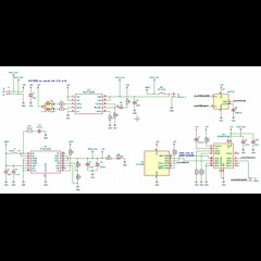
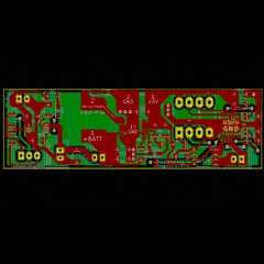
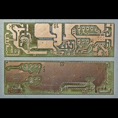
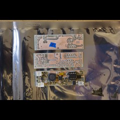
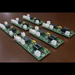
I was asked to create a motor controller board for a new product with a few other functionalities: a li-po change controller, a boost converter, a sensor, a microcontroller, and finally the motor controller itself. All of this needed to be packed in to an existing housing that was roughly 70mm x 20mm x 15mm.
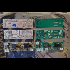
The working prototype from the client consisted of multiple chinese pre-made modules soldered together, requiring significant hand-assembly time leading to errors/issues from time to time and was bulky/fragile.
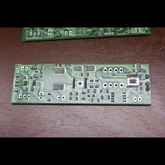
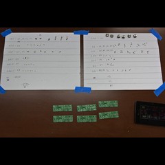
Since the chinese modules weren't well documented, I didn't really want to use them as a starting point, thus I was essentially starting from the ground up. After gathering the rest of the requirements, my first step was to research and prototype a few modules myself, figuring out which ones would be best given the constrains and to make sure there weren't any issues with my selections.
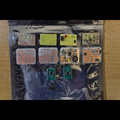
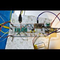
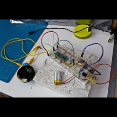
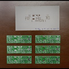
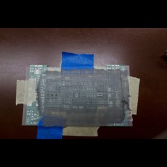
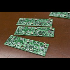
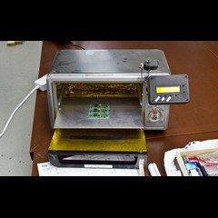
A few of these were made for more testing and given to the client for further testing. After few tweaks and improvements based on some insights in how they were being used by the client, and the next revision boards were fabricated, along with stencil aided assembly.
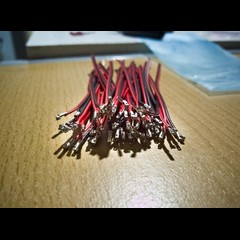
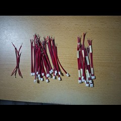
* I also had to hand crimp a whole bunch of jst connectors for the off-board parts. >.>